🡩
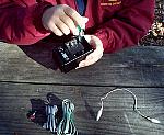
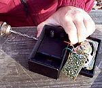
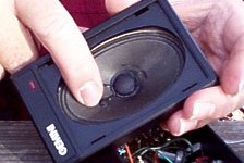
The first step is to open the speaker case. There are usually 4 screws on the back. On some models you may have to open the battery compartment to access one or more of the screws.
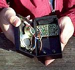
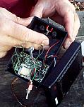
Remove the amplifier board. Determine the method used to hold the front grill in place and remove the grill.
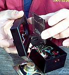
Removing the board will also be necessary to perform the soldering operations.
If the speaker has a built in input cord, this should be removed, but remember where the conductors were connected.
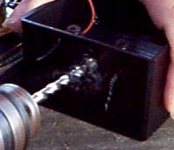
Drill 2 holes about ¼ to ½ apart (or just one if using the two color LED) of appropriate size in the speaker case to mount the LEDs in. Locate these holes where the LEDs can be seen while the user is holding the unit. Make sure the location you chose, will allow components to fit back in the case without the LEDs or wires getting in the way.
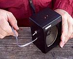
Drill another hole for the phone cord, again, locate to avoid interference with component placement.
If you are using the optional spst switch, drill another hole to accommodate the switch. This switch is used to turn on and off the phone connection without having to unplug the phone cord.
Cut the connector off one end of the phone cord. Leave about 1 or 2 feet of cable on the connector you are cutting off. This will be used if you make the optional alligator clip connections. If the wires are easy to work with and you need a source for the short wires in the project, cut about 6 inches more off the end of the cord and use those conductors for the short wires.
If you are using a single two color LED the following step is not needed.
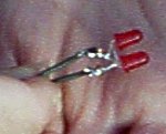
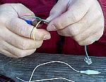
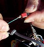
If you have chosen to use 2 LEDs, you will need to solder them together. Usually one of the LED's leads is longer than the other to indicate polarity. Connect the long lead of one LED to the short lead of the other. Then connect the remaining two leads together. If your LEDs have the same length leads, check the package for instructions as to how to determine polarity. Essentially you are connecting the + (plus) lead of each LED to the - (minus) lead of the other.
Strip ½ inch off both ends of a short length of wire (about 2 or 3 inches long) and solder one end to one of the connected LED leads. It does not matter which.
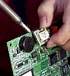
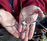
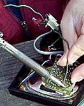
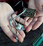
If you are getting the transformer from a modem, locate the component and remove it from the board by desoldering its pins. Be careful not to apply so much heat that the fine wires inside the transformer are damaged. Applying a bit of fresh solder to the connection will help the heat flow easier.
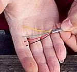
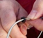
Strip several inches of the outer jacket from the end of the phone cord being careful not to cut the inner wires.
Cut off the black and yellow wires. Strip about ½ inch of insulation off the end of the red and green wires. Insert the phone cord through its hole in the speaker case and tie a knot in the wire on the inside of the case to prevent the cable from coming out. Alternatively you can use a cable strain relief.
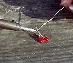
Solder the green wire from the phone cord to the remaining LED lead.
If you are using the optional spst switch, solder the short wire from the LEDs to one terminal on the switch. Prepare another short wire and solder it to the other switch terminal.
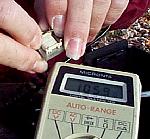 Determine which 2 pins or conductors are the primary on the transformer. This side should have about 600 ohms across the pins or leads.
 Some transformers have the same resistance on both sides, in that case you can use either one. If the coil does not read exactly 600 ohms, or the 2 sides have very different resistances, then use the coil with the highest resistance as the primary.
If you are using a transformer with wire leads, you can eliminate several of the short wires discussed and connect the transformer leads directly.
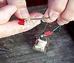
Connect the short wire from the LEDs (or from the switch if used) to one pin of the primary transformer coil. Connect the red wire from the phone line to the other pin of the primary coil.
Strip about ½ of insulation from each end of 2 more short pieces of wire. Solder one end of each of these wires to each of the secondary pins of the transformer.
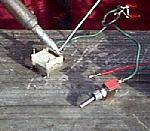
Locate the audio input points on the speaker's amplifier board. Solder the other ends of the two wires from the transformer secondary, to the audio input points of the amplifier board.
You need one connected to common or ground, the other to where the center conductor of the original cable connected. It may be useful to check the tester at this point.
Put batteries in the speaker and try plugging the unit into the phone line. If you don't get any sound, you probably have the transformer connected to the wrong points on the amplifier board.
If you used the optional switch, mount it in its hole.
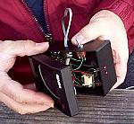
Push the LEDs through their holes in the speaker cabinet. If you have some type of mounting clips for the LEDs, use them. If no mounting clips are available, place a touch of non-plastic-melting glue around the base of the LEDs inside the cabinet to hold them in place. You can also use a bit of bathtub caulk, but you must let the caulk cure for several days before reassembling the speaker. The curing chemicals in the caulk can damage the electronics and speaker.
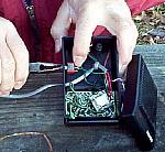
Replace the amplifier board in the speaker case.
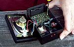
Mount the transformer in the cabinet where it won't interfere with any wires. A small piece of double stick foam or mirror tape works great for this.
Reassemble the speaker
If you installed the optional switch, label the on and off positions.
If the speaker does not have a power indicator, and its power switch isn't already marked, label the power switch as to on and off positions.
You are done.