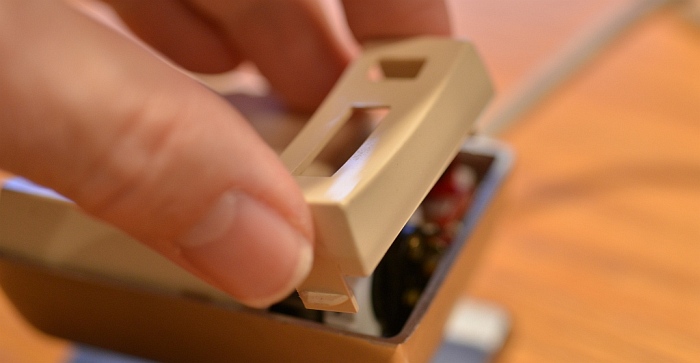
Squeeze the small section together and lift out 2
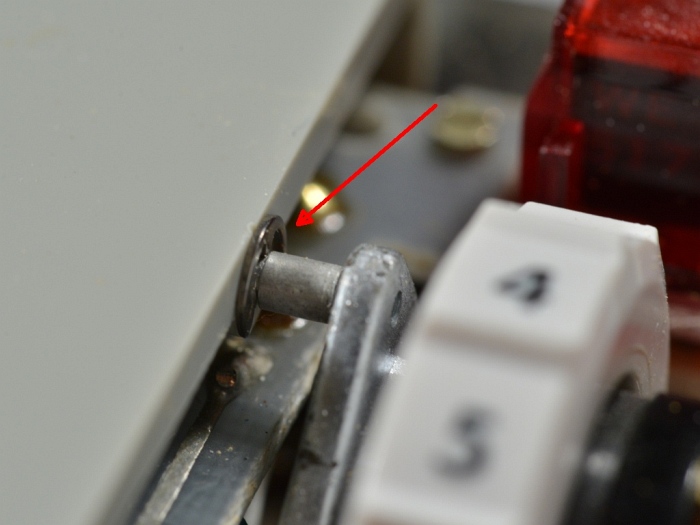
Gently pry large cover off with small screwdriver. 34
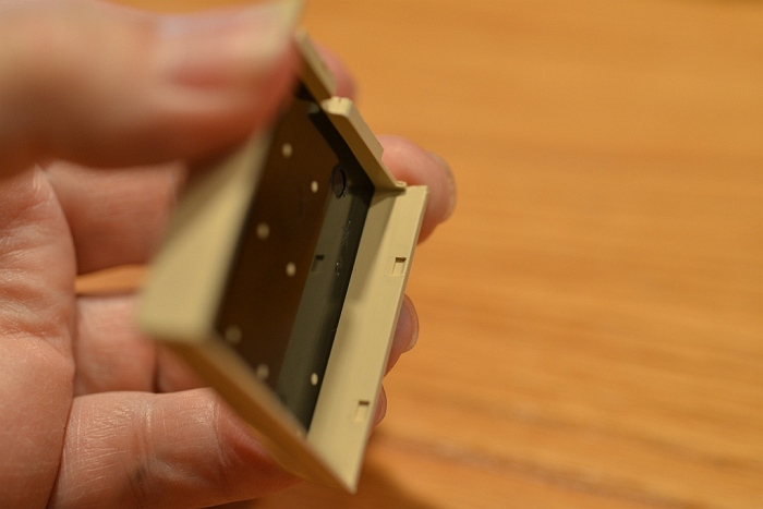
The underside of the cover
Notice the small rectangular dimples which capture the bumps on the rocker base which can be seen in the photo above or more clearly in photo 14 further down the page 5
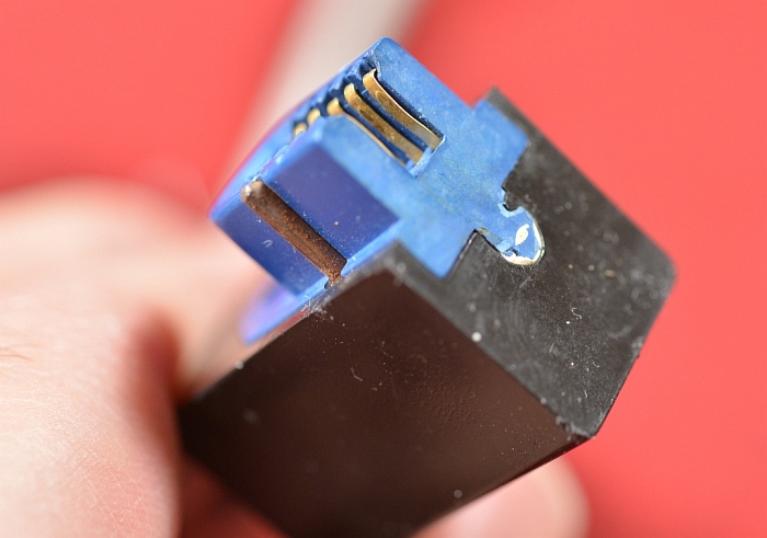
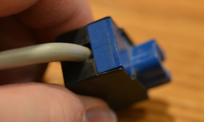
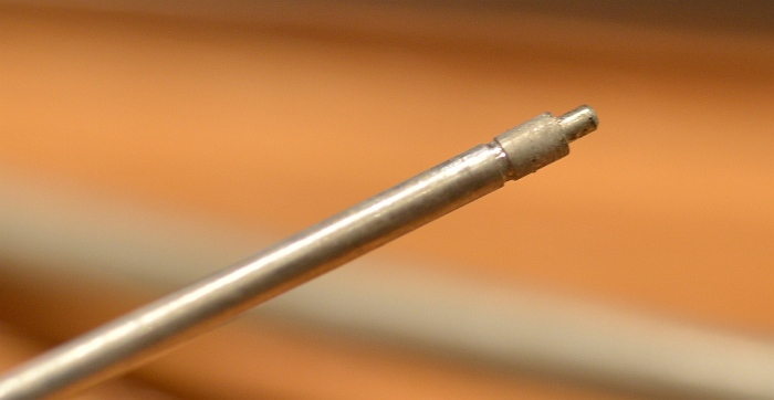
The brass alignment key
This pin doesn't seem to be connected to anything inside the plug. On closer scrutiny, it appears that they used a standard 50 contact Amphenol connector and cut off all but the 10 contacts on one end. I am now speculating this is an early production model connector. Since the connector wouldn't have had the alignment key molded in, they had to jury rig something to form the alignment key, thus the brass pin. This may have been one of the earliest plugs made before the molded key connectors were developed. 6
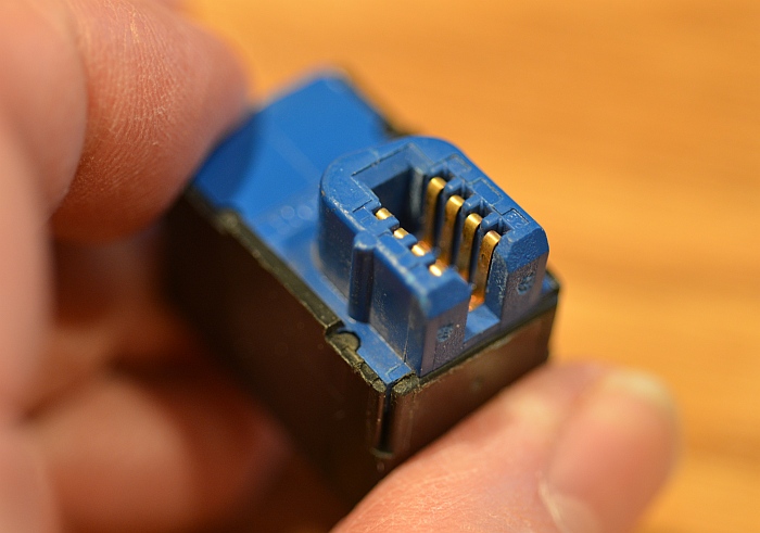
A later model from 1980
Notice the brass pin has been replaced with a molded rib 7
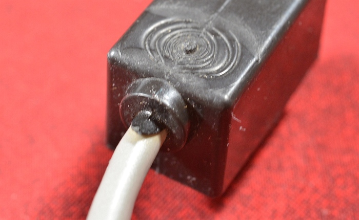
Completely molded plug
Wiring is probably soldered to pins, then the entire assembly went through an injection molding process 8
Later connector
This connector can be disassembled for repair if neccessary. Probably easer to produce too. 9
 Gently pry large cover off with small screwdriver.
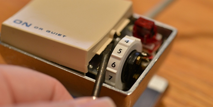 4
4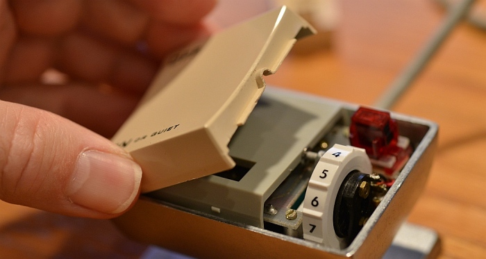
 15
15